DFM: Design for Manufacturing for CNC Milling
How to design parts for CNC vertical machining: pocket depth, internal corners, tolerances, wall thickness, hole and thread design, and material selection.
CNC vertical machining centres (VMCs) are among the most widely used methods for producing high-precision components. But moving into production without a well-optimised design leads to higher costs, longer machining times and avoidable quality issues.
This guide covers the key design considerations for CNC vertical machining, so you can create parts that are easier to manufacture, more cost-effective and able to meet demanding quality requirements. If you'd like a second pair of eyes on your design, contact the FastFab team.
What is CNC vertical machining?
CNC vertical machining is a subtractive manufacturing process in which the cutting tool moves along the vertical (Z) axis. It is typically performed on machines with three or more axes, which makes it possible to produce complex, high-precision components.
It is used to machine a wide range of engineering materials, including:
- Aluminium alloys: 5083, 6061 and 7075
- Steels: S235JR (1.0038, formerly St37-2) and C45
- Stainless steels: 304, 304L, 403 and 416
- Engineering plastics: Delrin (acetal/POM), UHMW, LDPE, HDPE and PEEK
Thanks to its accuracy, repeatability and versatility, CNC vertical machining is the preferred choice for precision parts across automotive, aerospace, industrial equipment, electronics and medical devices.
Why are there design rules for CNC machining?
CNC machining may look like it offers complete design freedom, but it is constrained by cutting tool geometry, machine capabilities and the physical limits of the process. End mill diameter, tool reach, vibration (chatter), workholding and cutting forces all influence how a part should be designed.
That's why CNC design guidelines are more than recommendations — they directly affect manufacturability, cost, machining time and final part quality. Designing with them in mind gives you:
- Shorter machining times
- Lower manufacturing costs
- Better surface finish and overall part quality
- Greater dimensional accuracy and process reliability
The most common mistakes in CNC part design
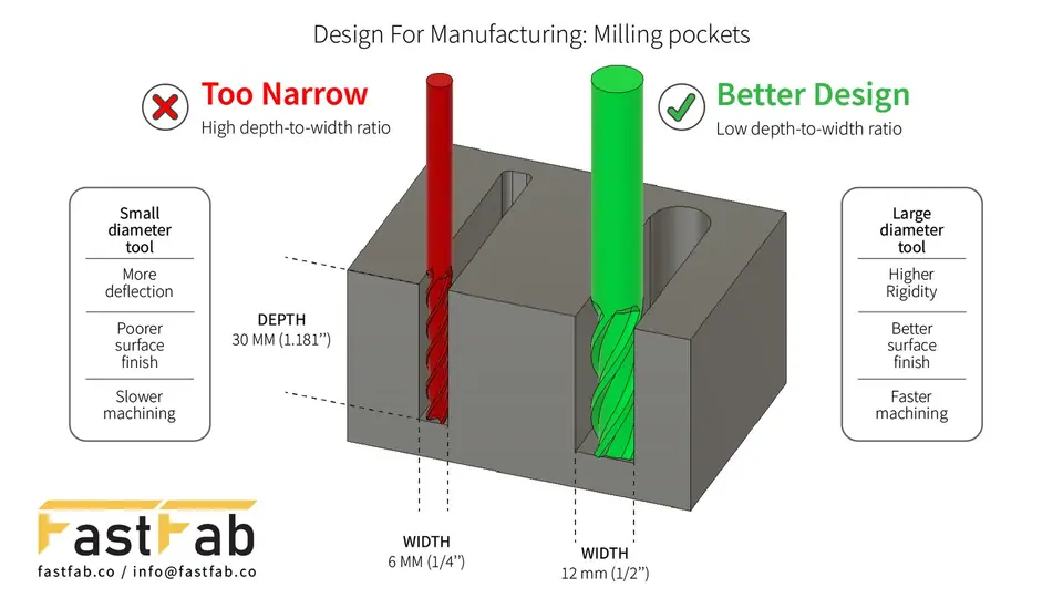
1. Unnecessarily narrow pockets
Deep, narrow pockets are one of the most common features that add machining complexity. They:
- Require smaller-diameter cutting tools
- Increase machining time because of lower material removal rates
- Raise the risk of tool deflection and breakage
Wherever possible, design pockets that are wider and more accessible. Larger pockets allow larger tools — faster machining, better rigidity and lower cost.
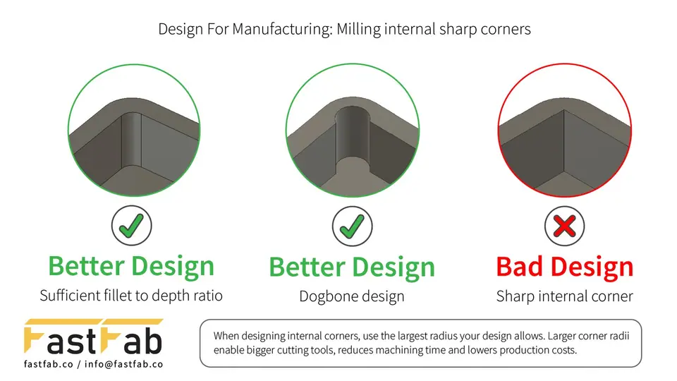
2. Sharp internal corners
Because end mills have a circular profile, perfectly sharp internal corners can't be produced by conventional milling. To improve manufacturability:
- Add an internal corner radius (for example R2 or R3) wherever possible.
- For mating parts that need square internal corners, use a dogbone relief. Standard tools can then fully machine the corner while the parts still fit together.
Corner radii and dogbones reduce machining time, minimise tool wear and remove the need for costly secondary operations.
3. Overly tight tolerances
Applying ±0.01 mm to every feature may feel safe, but it usually adds cost and lead time without improving the part. Over-tight tolerances:
- Increase machining and inspection time
- Require additional finishing operations
- Raise production costs without improving function
Apply tight tolerances only to features that are critical for fit, function or assembly, and use more relaxed tolerances elsewhere. At FastFab we work with customers to put precision where it matters — this design-for-manufacturing (DFM) approach removes unnecessary cost and shortens lead times.
CNC vertical milling design guidelines
Minimum tool diameter and pocket depth
One of the most important relationships in pocket design is between tool diameter and cutting depth. As a guideline, keep the depth-to-diameter ratio between 3:1 and 4:1.
Example: a 3 mm end mill should generally be limited to a cutting depth of about 10–12 mm.
Long tools are less rigid, so they vibrate and deflect more. That hurts surface finish, dimensional accuracy and your ability to hold tight tolerances — especially in deep internal pockets, where tool reach is often the limiting factor. Shallower, more accessible pockets allow shorter, stiffer tools.
Wall thickness
Walls that are too thin are less rigid and deflect under cutting forces. Excessively thin walls can:
- Increase vibration (chatter)
- Reduce surface finish quality
- Cause dimensional inaccuracy through deflection
- Deform, especially in aluminium and engineering plastics
Keep walls as thick as the design allows. When thin walls are functionally required, tool selection, machining strategy and workholding need to be optimised to keep the part accurate.
Hole design
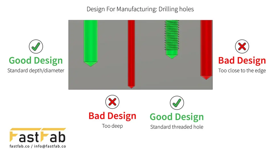
Designing holes around standard drill sizes is one of the simplest ways to cut cost: standard tooling means fewer tool changes and faster, more reliable machining. Also consider how close holes are to each other, to edges and to thin walls — holes placed too close can weaken the part and make it harder to machine.
For threaded holes, specify the standard tap drill size and enough thread engagement. As a rule of thumb, 1× the nominal diameter is sufficient in steel, while 1.5× is recommended in softer materials such as aluminium and many plastics.
| Thread size | Tap drill diameter | Recommended thread engagement |
|---|---|---|
| M3 × 0.5 | 2.5 mm | 3–4.5 mm |
| M4 × 0.7 | 3.3 mm | 4–6 mm |
| M5 × 0.8 | 4.2 mm | 5–7.5 mm |
| M6 × 1.0 | 5.0 mm | 6–9 mm |
| M8 × 1.25 | 6.8 mm | 8–12 mm |
Additional recommendations:
- Leave room for chip evacuation in blind holes.
- Avoid unnecessarily deep holes — they need longer, less rigid drills and take longer to machine.
- If a deep hole is unavoidable, consider machining it from both sides.
Material selection and machinability
Material choice affects not only machinability but also dimensional accuracy, surface finish, tool life and the risk of distortion. Even with optimised toolpaths and high-end machines, an unsuitable material can compromise the result.
This matters most for thin-walled parts and tight tolerances. Many materials contain residual stresses from rolling, forging, casting or heat treatment. As material is removed, these stresses are released and the part can warp — so consider machining behaviour, not just mechanical properties, during design.
6061 aluminium
- Advantages: excellent machinability, low tool wear, high-quality surface finish, good strength-to-weight balance
- Typical uses: aerospace and automotive components, industrial machinery, prototypes and production parts
- Design tips: choose stress-relieved 6061-T651 where possible. Thin-walled parts machined mostly from one side are more likely to warp.
7075 aluminium
- Advantages: very high strength-to-weight ratio, excellent mechanical properties, high hardness
- Typical uses: aerospace structures, defence, highly loaded mechanical parts
- Design tips: harder to machine than 6061 with higher cutting forces and tool wear. Residual stresses tend to be more pronounced, so distortion is more likely under aggressive material removal.
C45 steel (AISI 1045 / 1.0503)
- Advantages: high strength, widely available, good mechanical properties
- Typical uses: shafts, machine components, mould and fixture elements
- Design tips: machinability depends on hardness and heat treatment. Removing large amounts of material can release stresses and change dimensions.
4140 alloy steel (1.7225)
- Advantages: high strength and toughness, responds well to heat treatment
- Typical uses: mould components, tooling, heavy-duty mechanical parts
- Design tips: pre-hardened grades are much harder to machine; tooling, cutting parameters and strategy are critical to avoid distortion and excessive wear.
ST37 (S235JR) structural steel
- Advantages: relatively easy to machine, cost-effective, readily available
- Typical uses: structural components, frames, general-purpose parts
- Design tips: less consistent than C45 or 4140; surface finish and dimensional stability can be less predictable, and thin or precise parts may deform unexpectedly.
Stainless steel (304 / 316)
- Advantages: excellent corrosion resistance and durability
- Typical uses: food processing, medical devices, chemical processing, marine
- Design tips: considerably harder to machine than carbon steel or aluminium. It work-hardens quickly and runs hot, which shortens tool life and makes tight tolerances and fine finishes harder — good coolant and conservative strategies are essential.
See all the materials we machine on our materials page.
How to reduce CNC machining costs
1. Use standard cutting tools
Design features that can be cut with standard end mills, drills and taps. Special tooling adds setup cost, extends lead time and adds complexity.
2. Minimise the number of setups
Each time a part is re-clamped, fixturing, alignment and verification take extra time. Parts completed in a single setup are faster to make, more accurate, have better feature-to-feature alignment and cost less.
3. Remove unnecessary features
Decorative or non-functional details add machining time without engineering benefit — very small fillets, decorative pockets or grooves, needlessly tight tolerances, and complex geometry that doesn't improve performance. Keep the design as simple as its function allows.
Conclusion: better design means lower cost and higher quality
Successful CNC machining starts with a design that's optimised for manufacturing. Even small changes can significantly reduce machining time and cost while improving accuracy and quality.
At FastFab we help customers optimise their designs for CNC machining — whether it's a single prototype or full production. From DFM reviews and material selection to prototyping and production machining, our team works with you to deliver high-quality parts as efficiently as possible. Email info@fastfab.co or request a quote to discuss your project.